All-in-one Solution for Measurement & Inspection of Backlit Components
Recent attention and excitement in the automotive industry has been focused on displays, such as the latest prototypes of continuous OLED dashboard panels, touchscreens, and smart glass window displays. But traditional backlit signs and symbols are still a mainstay of automobiles, used for many controls and features within the vehicle. Backlit symbols are also still abundant in the aviation industry, on marine vessels, on industrial equipment, and on many electronic devices.

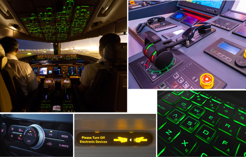
Backlit characters and symbols are used (clockwise from top left) in aviation, on navigation equipment aboard an aircraft carrier, for airline passenger safety, for illuminated keyboards, and for automotive controls. (Lower right image © Vobaga)
Backlit symbols are made from two components:
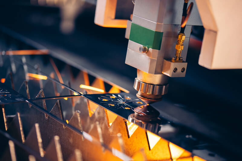
- A surface layer such as plastic with cut-out shapes (like a stencil). The shapes are typically made by a laser or plasma cutter. Any defects in the material or errors in the cutting process can cause defects, such as the wrong symbol shape or size.
- A light source (typically LEDs) placed behind the surface so illumination shines through the cut outs. Light source issues can include incorrect brightness (luminance) or color (chromaticity) of the symbol as a whole, or a lack of brightness and/or uniformity from one part of the symbol to another.

A plasma CNC machine cutting stenciled symbols in a metal sheet.
Once assembled, manufacturers need to inspect backlit panels to ensure product quality and usability for the end customer. Are symbols correct, legible, and in the right place and orientation? Does the illumination enable text and symbols to be visible under all ambient conditions?
Beyond the multiple quality criteria, product manufacturers in heavily regulated industries like automotive and aerospace must also comply with strict rules and regulations governing symbol appearance and performance. To meet these requirements and ensure the safety and satisfaction of operators and occupants, OEMs and suppliers need effective systems to measure and inspect backlit symbols.
Advanced Automated Visual Inspection of Backlit Symbols
Photometric measurement systems (colorimeters, photometers, and spectrometers) excel at light and color measurement. However, these systems have historically lacked the machine vision registration functions that enable measurement and defect detection within uniquely shaped regions such as symbols. For this reason, evaluating backlit components has required either multiple pieces of equipment or a complex, customized vision solution to ensure all inspection requirements are met.
Now, Radiant Vision Systems offers the first automated visual inspection solution that combines photometric measurement with machine vision image analysis and registration. Our VIP™ (Vision Inspection Pack) Software provides complete backlit component inspection in a single vision system. Used with a ProMetric® Imaging Colorimeter or Photometer, VIP and offers advantages over current systems for fast, hassle-free evaluation of backlit components in R&D and during production.
VIP performs inspection based on registration regions to ensure the integrity and overall quality of icons and shapes.
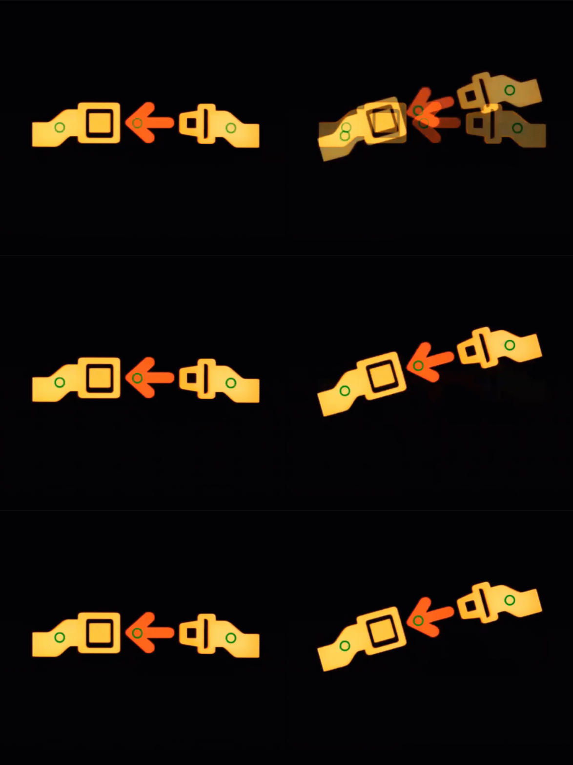
In addition to measuring the photometric qualities of the complete illuminated area of an icon, VIP allows custom points of interest (POI) to be applied within a registration region to evaluate photometric qualities of each icon based on POI values alone. VIP automatically locates and registers icons or shapes in new orientations (as components move or shift) while maintaining the same relative POI placement within each registration region. This ensures all icons in a series of components are consistently measured based on the same POI locations, without requiring users to maintain exact fixturing tolerances or reapply registration regions or POI locations for each component measured.

VIP maintains POI positions relative to the symbol under test, even if parts rotate or fixturing positions change.
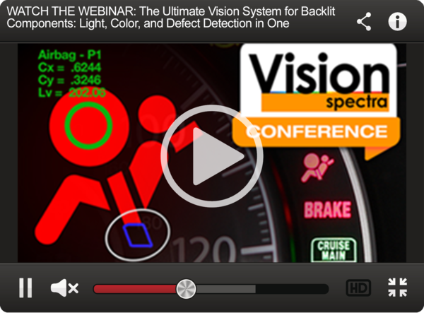
To learn more, watch our Webinar presented at the recent Vision Spectra Conference (with free registration): The Ultimate Vision System for Backlit Components: Light, color, and Defect Detection in One.

Join Mailing List
Stay up to date on our latest products, blog content, and events.
Join our Mailing List
