SIG-400
Precise measurement of near-field luminous intensity for LEDs and other small light sources.
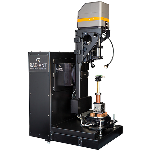
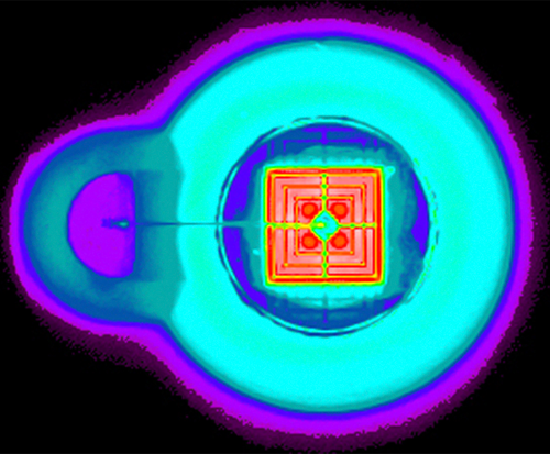
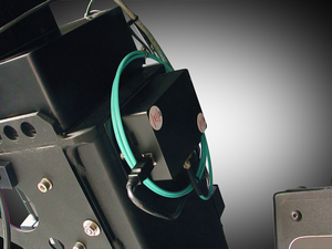
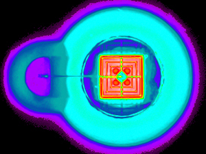
The SIG-400 (Source Imaging Goniometer® Generation 4) is a fully-automated, computer-controlled goniometric system designed specifically to meet the needs of LED researchers, developers, manufacturers, and users for LED die and device characterization. The SIG-400 uses a ProMetric® I Imaging Colorimeter to generate highly-accurate near-field models of LEDs. This data can be used directly to investigate the performance of the LED, or it can be exported using Radiant Vision Systems ProSource® Software, for use in all major optical design software packages.
Efficiency and Cost Savings
Focusing on LED measurement needs
By combining Radiant's latest advances in imaging colorimetry, robust mechanical design (to provide absolute accuracy), and easy-to-use control software, the SIG-400 can be readily applied to a broad range of measurement applications. By focusing on the needs of LED measurement, the SIG-400 is also very cost-effective.
The SIG-400 captures and aggregates images and flux measurements from thousands of angular viewpoints around a light source to precisely characterize the source's near-field output. The SIG-400 supports measurement of vertically-oriented light sources and can be ordered with both microscope and extended field-of-view optics, thus providing the flexibility to measure both LEDs and other light sources.
Complete Turnkey System
Generating accurate input for optical design
The SIG-400 system consists of a ProMetric® Imaging Colorimeter, a goniometric assembly for positioning the imaging colorimeter and the light source relative to one another, and SIG 2.0 Control and Analysis Software. The SIG-400 captures images of the light source from multiple angles, building a 3-dimensional spatial image of the color and luminance output of the light source. These measurements are aggregated into a Radiant Source Model™ (RSM) format, which is a detailed, industry-standard model for representing a light source's near-field data. RSMs contain all of the measurement information, including the image data, enabling measurement results to be reviewed in detail at any time. RSMs are used to compare the optical properties and designs of various LEDs and to generate input to the most common optical design software packages for use in luminaire and optical system design.
Applying Radiant's ProSource Software to the RSM, ray sets containing an arbitrary number of rays can be generated for export to other optical and illumination system design software packages such as ASAP®, FRED®, LightTools®, LucidShape®, Photopia™, IES TM-25, Opticad®, OSLO®, SimuLux®, SPEOS®, TracePro®, and OpticStudio™ (ZEMAX), as well as general file formats. Because the RSM is a complete description of the light source, it can be used to generate and regenerate ray sets at will. This provides smaller numbers of rays for rough design and a large number of rays for final design, making the overall design process more efficient.
Optical Specifications and Capabilities
| Sensor Type | CCD, Temperature Stabilized, Cooled to +5° C | |
| System Dynamic Range | > 60 dB | |
| Resolution | 592 x 592 | 1072 x 1072 |
| Standard Field of View (FOV) | 2.3 mm, 4.7 mm, 9.1 mm, 13 mm, 25 mm and 54 mm |
4.9 mm, 10 mm, 20 mm, 28.7 mm, 57 mm and 122 mm |
| Extended FOV: Micro (with SIG-400MF20 option) |
0.6 mm | 1.3 mm |
| Extended FOV: Micro (with SIG-400MF10 option) |
1.1 mm | 2.4 mm |
| SIG-400EF option | 98 mm | 212 mm |
| Color Measurement* | CIE 1931 matched XYZ filters | |
| Neutral Density Filters | ND 0, 1, 2, 3, 4, and 5 standard | |
| Measurement Capability | Luminance, luminous intensity Color: CCT; CIE x,y; u’,v’; ΔE |
|
* Photopic-only option available for purchase
Mechanical Specifications
| Overall Size | 71 cm x 56 cm x 125 cm |
| Operating Footprint | 74 cm x 127 cm |
| Azimuth Motion | 0° to 360° |
| Inclination | ± 140° |
| Angular Step Size | 0.10° minimum for both azimuth motion and inclination |
| Run Out | ± 0.015 mm mechanical-optical-software run out |
| Weight | 130 kg |
| Construction | Welded steel frame for thermal stability and rigidity |
SIG-400 Software
Current Version:
Ver. 2.3.11
Supported Products:
System Requirements:
- 3.0 GHz and 8 cores
- 16-32 GB RAM
- Windows® 10, 64 bit
- Ethernet 100/1000 or USB 2.0
Control and Analysis Software Features
| SIG Software |
|
| ProSource® Software |
|
Specifications subject to change without notice.

