Combining Computer Vision with Photometry for More Effective Backlit Symbol Inspection
When you're driving—especially at night—you depend on various lighted elements inside the vehicle to quickly check information such as speed, and to control vehicle functions such as navigation and climate settings. Sufficient and precise illumination of vehicle elements ensures that a driver receives the vital information they need to ensure safe vehicle operation. Any illuminated elements must be clearly visible to communicate necessary data in any ambient-light or environmental condition, whether you're driving in bright sun, on a cloudy or stormy day, or at night.
In recent years, advancements in LED technology, new display technologies such as OLED, and new freeform and curved display shapes have inspired automobile designers to incorporate a wider variety of illuminated elements into all areas of the vehicle interior. More displays, backlit instrument panels, illuminated controls, and lighting can be found in all the latest models. At the same time, a proliferation of sensor systems on vehicle are gathering an increasing amount of real-time information that is also presented to the driver—for example, back-up camera warnings and vehicle proximity alerts are shown on displays or as a lit icon on the dashboard or mirrors.
The dashboard is and has always been the most important location of visual information presented to the driver. It includes illuminated gauges, symbols, indicators, and warning lights to help the driver operate the vehicle and monitor its status. The vehicle center stack (the front panel in the middle between the driver and front passenger) also typically includes components such a backlit controls, illuminated buttons and dials, and display screens that present GPS, infotainment, and environmental indicators.
Because of their importance for safety, every illuminated vehicle component must meet strict industry regulations and standards—from headlamps and turn signals to dome lights and control buttons. Dashboard elements such as warning lights and indicators are required to meet strict specifications for luminance, chromaticity, clarity, and shape, and manufacturers must test them against standards for safety and performance as well as internal quality specifications. As vehicle technologies have evolved, the complexity of inspection regimens has evolved alongside.
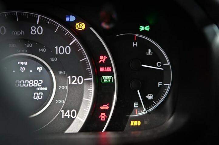
Typical backlit icons and symbols on an automotive dashboard.
Inspection Requirements for Illuminated Components
Testing the visual performance and quality of all lighted elements in the vehicle requires an inspection solution that can:
- Measure absolute values for luminance (brightness) and chromaticity (color)
- Measure the uniformity of luminance/chromaticity across a backlit area
- Evaluate of the shape and completeness of illuminated text, numbers, and symbols to identify defects such as inclusions or exclusions
- Assess a symbol’s quality, completeness, and position even if it's rotated or moved
- Capture test and inspection data to meet the reporting requirements of standards and certification entities
- Perform all of the necessary evaluations at rapid speed in a production environment
Existing Systems. Typically, automakers have used a combination of methods to perform the needed inspections. However, each method only provides a partial solution:
- Spot Meters – provide absolute luminance and chromaticity measurement, but only for a single small area (spot) at a time. These meters have no ability to evaluate shape completeness or detect dimensional defects.
- Human inspectors – can quickly discern symbol shape, orientation, and completeness, but not absolute luminance and chromaticity. Additionally, these inspectors are costly to employ and subject to fatigue and error.
- Machine vision cameras – can match characters, shapes, and symbols accurately compared to a golden sample for completeness inspection and defect detection. However, they cannot measure absolute luminance and chromaticity. These systems also may not be able to perform a test if symbol location and orientation changes or if the part under inspection is not perfectly aligned—as frequently happens with the laser-cut components on the production line. This issue requires complex fixturing for the inspection set up.
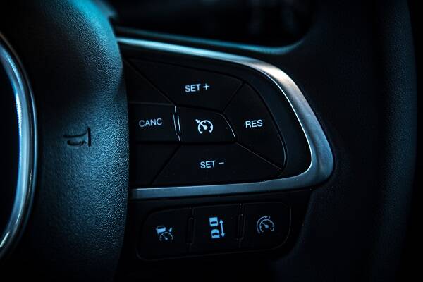
Both color (chromaticity) and brightness (luminance) of backlit indicators must be uniform and meet precise regulatory specifications.
A New Inspection Solution: Machine Vision Capabilities + Photometry
Radiant’s decades-long history of developing photometry-based solutions for light and color measurement in the automotive industry has put us in a unique position. While we have had photometry as our foundation, additional inspection needs around lighted components have provided an opportunity for us to develop expertise in addressing some of the more challenging machine-vision problems in areas such as surface and glass inspection and assembly verification. Bringing our experience and capabilities together, a new solution was born: VIP™ (Vision Inspection Pack) Software.
VIP is a set of machine vision tools built on top of our TrueTest™ Automated Inspection Software platform. Combined with a ProMetric® Imaging Photometer or Colorimeter, VIP provides complete measurement of component luminance, chromaticity, and defects in a single image. VIP brings together the science of photometry-based imaging and the toolset of machine vision in one solution, giving automotive manufacturers a complete array of options to address inspection needs.
Perceiving a Need for Better Symbol Inspection
There are dozens of types of illuminated components in automobiles, often manufactured by different suppliers. This can introduce slight variations between different parts in the same vehicle, different production runs by the same supplier, and between lots of the same part received from different suppliers.
As just one example, consider blind-zone indicators: the warning symbols that light up to alert a driver if there is another vehicle in the blind spot, helping to prevent a collision. The indicators are typically manufactured by laser cutting a stencil layer that will overlay an illuminated panel, with light shining through to illuminate the symbol.
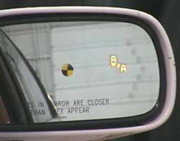
The blind zone indicator (right illuminated image of two vehicles positioned together) from a Buick Lucerne’s right-side mirror. (Image: NHTSA1)
As a critical vehicle safety component, backlit indicators are subject to strict visual requirements, including luminance and chromaticity values, shape, and position. They must be clear, visible, and legible under all ambient conditions. Yet they are particularly challenging to inspect, where fixturing (holding a part in place for inspection) can be difficult. Millimeter differences in laser cutting or part placement for inspection can interfere with effective measurement by machine vision systems.
Due to the limitations of traditional inspection systems, blind zone indicator components typically have to be inspected in two phases. First, the part is inspected by a machine vision system to ascertain shape and completeness of the symbol, ensuring there are no form defects such as inclusions (additional lit areas) or exclusions (dark areas that should be lit). Next the part may be inspected with a photometric system to measure luminance and chromaticity values of the illuminated elements.
Backlit symbols must be inspected for defects in their shape and formation, such as gaps (exclusions, left) or extra elements (inclusions, right).
In practice, this multi-phase inspection might mean a technician has to move each part between two different inspection stations—inspecting it twice. This is time consuming and costly, requiring more inspection time, labor, floorspace for multiple pieces of equipment, and purchasing multiple inspection systems. It also has the potential to introduce variations from one inspection to the next.
With VIP, however, comprehensive symbol inspection for shape, orientation, illumination, and color can all be performed by a single system, in a single measurement image. Using the VIP solution, manufacturers have been able to consolidate two inspection lines into one, thus reducing inspection time and labor. At the same time, VIP captures a complete set of data needed for both internal quality control and for reporting to regulatory bodies that monitor standards for instrument display such as, in the US: MIL-DTL-7788 (formerly Society for Automotive Engineers SAE AS7788) and Federal Motor Vehicle Safety Standard FMVSS 111; and equivalent global standards such as those from JASO (Japan) and DFF (Germany).
The Power of Dynamic Registration
Traditional machine vision systems are limited in their ability to accurately assess illuminated regions that may be rotated or appear outside of a fixed position. Another advantage of VIP is its ability to perform dynamic registration. Regardless of slight changes in position or orientation of components or component features, VIP can locate and register regions of interest (ROI), simplifying component placement and fixturing.
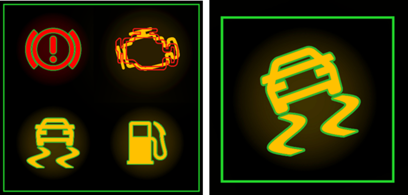
VIP automatically registers icons and shapes based on trained registration regions. Global registration (left) ensures icons are accurate relative to one another. Local registration (right) ensures icons can be accurately measured and inspected regardless of location or orientation.
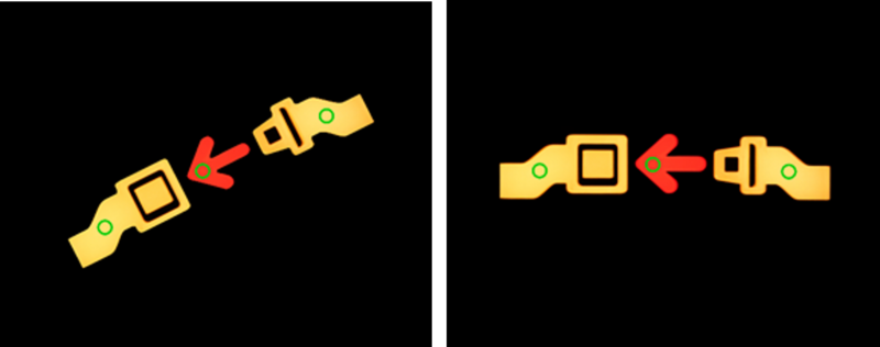
The aviation industry also has inspection requirements for backlit icons and symbols, such as these passenger fasten safety belt icons. In this case, quality is determined by measuring the symbol at defined POI (point of interest) locations (green circles). The position of these POI must be maintained for accurate inspection, regardless of whether the symbol is rotated relative to the inspection system.
For automakers tasked with ensuring the quality of illuminated components, the equivalent need for light measurement, completeness inspection, and defect detection has been a long-standing challenge in need of an efficient solution. VIP Software provides the only solution on the market with all these capabilities combined—and offers the unique flexibility to perform dynamic registration for additional ease-of-use. VIP was recently recognized with a Vision Systems Design 2021 Innovators Award, providing independent confirmation of the distinctive, breakthrough nature of this solution.
Learn more about VIP (Vision Inspection Pack) Software.
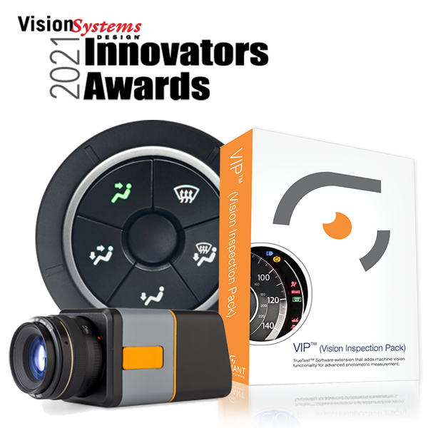
Radiant ProMetric Imaging Photometer and the VIP Software toolkit.
CITATION
- Forkenbrock, G., et al., Blind Spot Monitoring in Light Vehicles – System Performance. Report No. DOT HS 812 045, July 2014, Washington, DC: National Highway & Traffic Safety Administration.
Join Mailing List
Stay up to date on our latest products, blog content, and events.
Join our Mailing List
