Measuring Near-IR Sources for Facial Recognition and 3D Sensing
Near-infrared light—the range of electromagnetic wavelengths between roughly 700 nanometers (nm) and 1500 nm—is invisible to the human eye, making it ideal for an increasing number of 3D sensing applications such as facial recognition, iris scanning, gesture recognition, terrain mapping, automobile LiDAR, and night-vision security cameras.
Combined, 3D imaging and sensing is projected to become an $18.5 billion market by 2023, with far-reaching application in the consumer electronics, scientific, defense/space, law enforcement/security, automotive, medical, and commercial/industrial sectors.1
NIR Facial Recognition
One of the most talked-about uses of 3D NIR sensing technology is facial recognition. Several smart phone models have been released in the last 18 months that include this feature as a form of biometric security, allowing a user to unlock their phone simply by looking at it. Two-dimensional image-based facial recognition systems have been around for a while, using algorithms to analyze photographic images to match facial features. One advantage of NIR-based sensing systems is that they aren’t affected by different ambient lighting conditions, and can perform effective identification from different angles, such as a profile view.
These systems are able to sense 3D objects by projecting NIR light in a grid or dot pattern towards an object (like a person’s face). Typically, a diffractive optical element (DOE) is used to refract an NIR light beam into a dot pattern. The pattern is reflected off the object back towards the device and captured by an NIR camera. Algorithms then analyze the reflected data for any deformation from the original grid pattern, creating a 3D “map” of facial features, which can be matched against stored data to confirm a user’s identity.
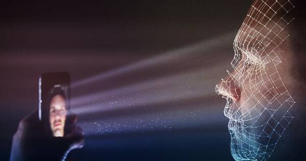
Illustration of smart phone facial recognition, where an NIR structured light pattern is projected towards a person’s face, reflecting off the contours of their features to create a 3D image.
Quality Considerations for NIR Sensing Systems
NIR emissions for 3D sensing applications are commonly produced by LEDs (light emitting diodes) and lasers. With the rapid adoption of sensing systems comes a growing demand for effective methods to measure the quality, performance, and accuracy of NIR emitters. NIR systems can be subject to performance issues such as inconsistent intensity, low-output, or poorly-placed emission points.
While NIR wavelengths are invisible to humans, they can still enter the eye and—with prolonged exposure—cause damage to the retina or cornea. NIR devices, especially those used for facial recognition and eye detection, must be carefully designed and tested to ensure they are emitting at the correct levels of intensity.
To qualify emissions used for facial recognition, a measurement system needs to address the 810-960 nm range that’s typical for NIR sources used in these applications. Ideally, a measurement system captures a variety of different characteristics such as emission uniformity, maximum power or intensity, radiant flux, emission distribution or spatial position—and it measures these parameters across the entire distribution area.
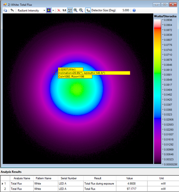
Example of a Total Flux analysis of an NIR LED over angular space, shown in a false-color scale using Radiant’s NIR Intensity Lens and TrueTest™ radiometric light measurement software. Radiant flux is a measure of radiant energy emitted per unit of time, e.g., Watts (joules per second).
Challenges of Testing NIR Emitters
In addition to the quality considerations described above, facial recognition systems present another challenge for NIR performance evaluation. Capturing NIR light in angular space—especially when identifying up to 30,000 emission points produced by today’s smart device DOEs—is extremely difficult for traditional measurement equipment. The use of image-based NIR measurement systems (for example, an image-based radiometric camera such as Radiant’s ProMetric® Y16 Imaging Radiometer) for NIR source measurement can limit this complexity by capturing and measuring all emission points produced by a DOE across a large spatial area.
To analyze the entire emission area that will cover a face, the testing device must quickly capture and evaluate a large angular distribution at close range. A wide-angle scope is needed to accomplish this, since the NIR-emitting device is typically positioned at a short distance (such as a smart phone held in a user’s hand).
An NIR light—like any light source—emits light in three-dimensional angular space. As such, each dot in a DOE pattern may vary in intensity or position based on emission angle. Measurement of the NIR DOE pattern must be performed at each emission angle to ensure that DOE patterns are accurately projected and that each dot has sufficient intensity to be received and correctly interpreted by the device’s NIR sensor.
Angular Measurement Solutions
To evaluate the intensity of NIR emissions across angular space, a device manufacturer may employ a goniometric measurement system. A goniometer rotates an NIR light source in front of a photodetector or camera to capture two-dimensional images of emissions at each angle. This process is time-consuming, requiring thousands of rotations to capture a complete angular measurement.
Furthermore, gaps in measurement can occur between goniometric rotations, missing irregularities in NIR intensity at certain points. Because NIR emissions can be dangerous to human vision, missing any angular data point during goniometric measurement may mean missing an irregularly strong emission that could prove hazardous to the user, especially over time.
An alternative to goniometers is a camera combined with Fourier optics, which eliminates the need for device rotation by capturing angular emission data from a single point. Lenses designed using Fourier optics principles enable connected imagers to characterize the full angular distribution of a light source, leaving no gaps in measurement. Advanced NIR measurement systems such as Radiant’s NIR Intensity Lens solution can characterize radiant intensity (strength, measured in Watts per steradian, or W/sr) of an entire NIR light source distribution in 3D space (to ±70°), identifying irregularities, peak emission, hot spots, and other issues.
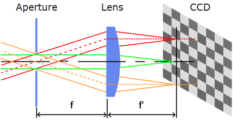
Illustration of Fourier optics directing angular emissions of light through the specialized lens onto points on an imaging system’s sensor, forming a 2D polar plot of the 3D distribution.
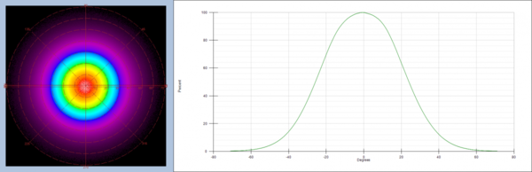
Radar plot and cross-section showing radiant intensity (as function of angle) of an infrared LED. The Fourier-optic lens is calibrated to its connected imaging system, allowing it to accurately map angular emissions of the NIR device to ±70° at once.
DOE Measurement Challenges
When evaluating NIR DOE emissions for facial recognition it’s imperative to assess every single dot for performance and accuracy. Until recently, the method for measuring DOE emissions was limited to checking dot patterns for accuracy by mapping them against ideal patterns or coordinates (typically with the NIR light pattern cast against a screen or wall). However, this method relies on a static pattern match and does not dynamically adapt to new DOE patterns. This method also cannot report precise radiometric data of the DOE emission points, providing only dimensional evaluation and simple pass/fail analysis.
Each dot in a facial recognition DOE array must be accurately positioned (angle, inclination, azimuth) and emitted with the correct radiant intensity to ensure it is properly reflected back and “understood” by the device’s infrared sensor. Manufacturers must control the position and output of each dot for the device to correctly map facial contours. For thorough evaluation of dot-by-dot performance, the ideal system should identify points of interest across the image, measure values for each dot in the DOE pattern, and evaluate the accuracy of the pattern as a whole.
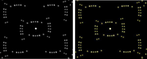
A sample DOE dot pattern before (left) and after analysis (right) using automatic dot detection in Radiant’s TrueTest™ Software. The software measures maximum peak (strongest emitter), maximum peak location (inclination/azimuth), maximum peak averages, maximum peak solid angle, number of pixels as maximum peak point, spot power uniformity (between dots), total flux, and DOE flux, along with dot-by-dot measurements for comprehensive analysis.
NIR Measurement – See It in Action
If you’re planning to attend the SPIE Photonics West conference February 3 – 7 in San Francisco, you’ll have an opportunity to hear more about the latest in NIR technology and applications. Come see us during the Photonics West Exposition (booth #3113), where we’ll be demonstrating Radiant’s NIR Intensity Lens solution and our AR/VR Lens solution, a specially designed lens option for near-eye display testing within augmented and virtual reality headsets.
Visit Radiant at Photonics West Booth #3113
CITATIONS
1. 3D Imaging & Sensing 2018, report by Yole Développement, March 2018. LINK
Join Mailing List
Stay up to date on our latest products, blog content, and events.
Join our Mailing List