Quality Considerations for Aviation Head-up Displays (HUDs)
In movies, we've all seen the dramatic air combat sequence where a pilot uses guide lines to zero in on a target before firing a weapon. Those on-screen guides are a head-up display (HUD), so called because the pilot doesn't have to look down at an instrumentation panel.
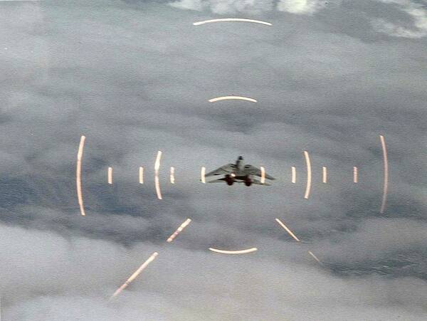
U.S. Navy Grumman F-14A Tomcat pictured in the crosshairs on the HUD of another aircraft during air combat maneuvering, 2013. Photo: By U.S. Navy [Public domain], via Wikimedia Commons
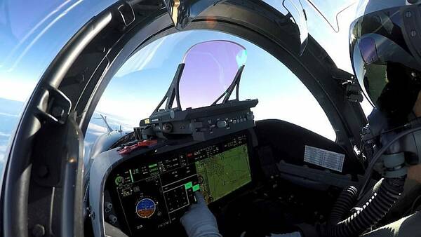
A head-up display (HUD) is any transparent display that gives a pilot a seamless view of critical flight information. This information is projected directly in the pilot's line of sight (e.g., on a screen just inside the windshield), allowing them to keep their visual attention focused outside the aircraft. Aviation HUDs are designed so that flight information appears to be on the same visual plane, so pilots don’t need to refocus their eyes when looking back and forth between projections on the screen and the exterior environment.
Rudimentary HUDs were first developed for World War II aircraft, and became widely used in military applications during the 1960s. The first civil application of the technology was introduced in 1993.1 Today, these systems are commonplace in both military planes and large commercial jets. Because of the weight and complexity of conventional HUD systems, they are less common in smaller aircraft. The Boeing 787 is the first large commercial aircraft to offer a HUD as standard equipment, using a Rockwell Collins head-up guidance system.
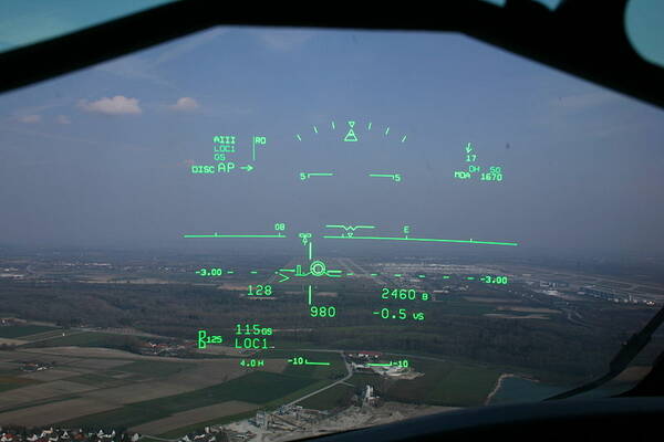
HUD in a Bombardier CRJ-200 displays the horizon line and other key flight information at 1000 ft. to assist with a smooth landing. Photo: by Shawn from Airdrie, Canada (CRJ HUD) [CC BY-SA 2.0 (https://creativecommons.org/licenses/by-sa/2.0)], via Wikimedia Commons
Conventional HUDs display key information and data (numbers and letters along with weather, navigational, and other symbols, collectively referred to as "symbology"). The symbology can include aircraft position information like altitude, a horizon line, heading & flight path, turn/bank & slip/skid indicators, radar data, and airspeed, along with other data from the plane's avionics and instrumentation (HUDs on military aircraft may also display information about the mission, such as an attack target, weapons status, etc.)
Pilots find HUDs particularly useful during take-off and landing, especially if visibility conditions are poor. In fact, the Federal Aviation Administration (FAA) now allows pilots to make landings in “no natural vision” (zero-visibility) situations as long as there is an "enhanced flight vision system" (EFVS) installed, for example, an aircraft HUD system, or a helmet-mounted display HMD) for the pilot.2
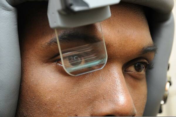
Scorpion HMD system being tested by U.S. Air Force Senior Airman Dieri Dieujuste. The system provides targeting and tracking information in real time. Photo: By SSgt David Dobrydney [Public domain], via Wikimedia Commons
HUD System Components
To operate effectively, a HUD system typically includes the following equipment and components:
- A computer that receives data (including real-time metrics from the aircraft system sensors, avionics instrumentation, and satellite data).
- A transparent display screen, called a combiner. Typically made of glass or plastic, the combiner reflects information towards the pilot’s eyes without obstructing the exterior view through the windshield or blocking the passage of ambient light.
- A control panel that allows the pilot to select various display options and data to be displayed.
- An overhead unit that projects the assembled images onto the combiner screen. Modern HUD systems have eliminated the projector unit and instead are able to generate images directly on the display screen.
First-generation HUDs used a cathode-ray tube (CRT) display to generate images on a phosphor screen. Many HUDs still in use today are CRT displays, but the phosphor screen coating degrades over time. Next-generation HUDs introduced the use of solid state light sources such as light-emitting diodes (LEDs), modulated by a liquid-crystal display (LCD) screen to display images. Many commercial aircraft use this type of HUD.
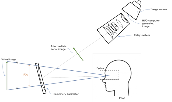
Schematic diagram of a conventional cockpit HUD.
Third-generation aviation HUDs use optical waveguides that produce images directly in the combiner, without the need for a projection system. Some of the latest HUD systems use a scanning laser, which can display images and video on a clear transparent medium, such as a windshield. HUD makers are also beginning to work with imaging technologies like liquid crystal on silicon (LCoS), digital micro-mirrors (DMD), and Organic Light Emitting Diodes (OLED) to reduce the size, weight, and complexity of HUD systems. The next generation of HUD technology adds synthetic terrain or infrared video information to further enhance the display, as part of a broader category of Enhanced Flight Vision Systems (EFVS) that includes conventional HUDs.
A new, smaller LightHUD® digital display by BAE Systems can be installed to upgrade aircraft with older CRT displays.
Human Factors in Aviation HUDs
The study of human factors is about understanding human behavior and performance. In the aerospace industry, discussion of human factors often focuses on the element of human error in accidents and system failures. Here, it refers to specific aspects of human capabilities and performance such as visual perception. Consideration of innate human characteristics and responses helps with optimal design of systems that will be used by humans (the discipline of human-centered design). Well-designed equipment and the quality of systems and components help reduce human factors as a causal element in poor performance and accidents.
For humans, the eyes (and the associated optic system and visual processing centers of our brain) are the most important source of information we use to assess and understand the world around us. Human vision has driven much of the evolution in cockpit technology. “In contrast to the complicated, gauge-based systems of the past, the electronic flight displays of today’s modern airliners are testament to advances in human factors engineering.”3 Some of the most important human factors considerations include:
- Focus & Accomodation. For the eye to “register a sharply focused image, certain structural alterations are required depending on the focal length or distance to the object of interest. The process of adapting focal length from a distant object to a near point is known as visual accommodation and involves three separate, but coordinated functions—lens accommodation, pupil accommodation, and convergence. The speed at which accommodation occurs varies between individuals and with age but it is generally a split-second affair.”3 Accordingly, a display configuration that requires the pilot to switch focal point from near (display screen) to far (exterior landscape) could potentially diminish the pilot’s performance, not enhance it.
- Visual Attention. Our brains are only able to process a limited amount of visual information simultaneously. We have visual working memory that helps process and buffer the information we take in, effectively “metering’ competing stimuli. However, focusing on specific items also blocks out others, potentially causing an “attentional blindness.” This selectivity is essential for a human’s ability to operate in complex environments “but also potentially dangerous when flying an aircraft… To efficiently attend to various information sources, and appropriately balance their time between focused and divided attention, pilots are taught the process of ‘scanning’, or attending briefly to each information source sequentially in a systematic fashion.”3 HUD displays reduce complexity by overlaying visual information on the exterior environment, making it easier to take in both types of visual input at once.

Is this all just "too much information" for our visual attention capacity?
- Color and Contrast. Correct color and contrast values in a HUD display are essential for usability and safety in all operating conditions. The human eye is very sensitive to color and luminance (brightness). We are more sensitive to contrast than absolute luminance, allowing us to see accurately over a wide range of lighting conditions. High contrast (for example, black text on a white page) is easier to perceive than shades of gray. Successive contrast is the effect on our perception in a dynamic situation when shifting our eyes between one or more objects or views in succession. For example, looking at bright cockpit lights then transferring attention to a dark sky causes reduced perception because our eyes take longer to adjust to the darker view. HUD systems typically use green light for their display symbology because the human eye is most sensitive to these wavelengths.
Design Factors
Constructing an effective HUD system relies heavily on the design of the display itself. Considerations about the size, form factor, lighting, and more must be carefully evaluated. Factors include:
- Field of View (FOV) – FOV is the scope of the angle (vertical, horizontal, and diagonal) that a display captures and transmits back to the pilot. For example, a combiner with a narrow FOV might show only a runway; a wider FOV could include more information around the perimeter of the runway, allowing the pilot to see peripheral objects like another plane approaching from the side.
- Parallax – Because human eyes are separated by a slight distance, each eye receives a slightly different image, which is combined in our brains to create our binocular vision. Parallax errors occur when the image presented on a HUD does not align eye-to-eye. A HUD image needs to be clearly viewable by one or both eyes. This issue is typically addressed by collimation.
- Collimation – The human eye can focus on only one point at a time, thus HUD images need to be collimated: the projected light rays need to appear parallel out to infinity, rather than appear to converge at a point on the physical display screen. With collimation, a pilot does not need to refocus to view both projected symbols and the outside environment since both appear to be on the same “infinite plane.” In time-sensitive and safety-critical maneuvers such as landings, eliminating even the brief time it takes a pilot to refocus from the digital projection to the outside view can be vital. A collimator is a key component of high-quality HUD systems.
- Eyebox – To enable collimation and clarity of the display, the user’s eyes cannot be too far outside of an optimal viewing position, defined as the head motion box or “eyebox” area of the HUD system. Move to far left/right, up/down, and the image may not display clearly or fully, or may be distorted. Modern HUDs allow some freedom of movement within an eyebox of roughly 5 inches lateral by 3 inches vertical by 6 inches longitudinally (front to back). For a quality HUD, the pilot needs to be able to view the entire display as long as one eye is inside the eyebox.
- Luminance/contrast – A HUD must adjust luminance and contrast depending on ambient lighting (sunlight, night conditions, weather, etc.) to ensure readability under all conditions.
- Boresight – Aircraft HUD components need to be precisely aligned with three axes of an aircraft, so that data on the display conforms to the plane’s real position in space—that is, relative to the artificial horizon. This alignment process is called boresighting. This is typically done to an accuracy of ±7.0 milliradians (±24 minutes of arc), and may vary across the HUD’s FOV.
- Scaling – The images displayed on the HUD must be scaled to overlay the outside view with a 1:1 relationship with respect to the flight path, (pitch and yaw scaling, landscape details, etc.). “For example, objects (such as a runway threshold) that are 3 degrees below the horizon as viewed from the cockpit must appear at the −3° index on the HUD display.”4
Quality Regulations
Because of their use in real-time flight situations, visual performance of HUD systems is critical. The FAA has issued several Advisory Circulars on topics related to HUD displays and electronic flight displays. Among many operational considerations, the agency specifies parameters related to a display’s size, resolution, line width, luminance (in all light conditions), contrast ratio, chromaticity, gray scale, response, refresh rate and update rate, defects (such as element defects and stroke tails), reflectivity/glare, and the size of the “flight deck viewing envelope."
For more detailed specifications, refer to the FAA Advisory Circulars:
- AC-25-11B – Electronic Flight Displays
- AC 90-106A – Enhanced Flight Vision Systems
- AC-25_1329-1C – Approval of Flight Guidance Systems
- AC-20-167A – Airworthiness Approval of Enhanced Vision System, Synthetic Vision System, Combined Vision System, and Enhanced Flight Vision System Equipment
Testing Head-Up Display Quality
How can aerospace manufacturers ensure that HUD equipment and systems are designed effectively to mitigate human factors, address the design and functional considerations, and adhere to FAA guidelines? A rigorous display testing regimen must be put in place. Thorough design and quality control inspection ensures that HUD projections are properly aligned and clear for in-focus binocular viewing, and that light and colors are vivid enough to be clearly discernible from surroundings in any lighting condition. Low-quality projections put aircraft at risk if operators are unable to interpret poorly-projected objects in the viewing area of the display. This can lead to misinterpretation, loss of critical environmental data (such as navigation, object proximity, and other alerts), and pilot distraction
To accurately assess these elements, an optical measurement device is used to test HUD projections at several measuring points within the eyebox area (to account for the scope of potential viewing angles). Radiant Vision Systems has provided the leading solutions for near-eye-display (NED) testing in consumer electronics and HUD testing in the automotive industry, with advantages for testing speed and simplicity. These applications have many similarities to HUD applications in aerospace. In contrast to test methods that use spot meters or traditional human inspection, Radiant offers all-in-one, automated, photometry-based HUD inspection solutions that can evaluate an entire display for all photometric and dimensional requirements in under two minutes. Radiant ProMetric® systems have been applied in various testing environments to measure see-through display technologies from OLED to waveguide, using a range of projection methods.
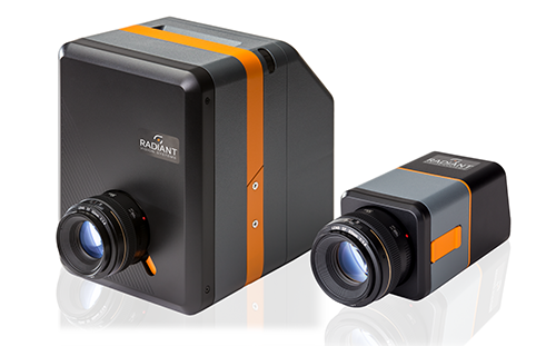
Radiant's ProMetric Imaging colorimeters and photometers are advanced imaging systems with optical components that simulate human visual perception of light and color. Many systems include beneficial features for automated HUD measurement such as electronic lenses, dynamic point-of- interest creation, and multi-step test sequencing software.
Radiant systems can measure luminance, contrast, chromaticity, uniformity, and other factors necessary to accurately evaluate HUD performance, using optical components that are designed to simulate the photopic and colorimetric response of the human eye. Radiant cameras feature electronically-controlled lenses with Smart Control™ functionality for precise, adaptive adjustment of focus and aperture settings. Combined, these technologies enable the fastest and most accurate location of illuminated objects projected on an infinite plane, such as HUD symbology. With minimal adjustment, Radiant imaging colorimeters map points of interest to projected symbols and provide luminance and color measurements while recording object distance, size, and scale at any working distance to ensure accurate projection.
Want to know more? Let us show you how Radiant imaging photometers and colorimeters solve a number of test and measurement challenges in the aerospace industry.
To learn more about Radiant's work testing HUD displays in the automotive industry, including our fully-automated solution for meeting industry requirements of the SAE (Society for Automotive Engineers) according to J1757-1 and J1757-2 standards, read the white paper:

Footnotes:
- "Head-Up Display" on SkyBrary, https://www.skybrary.aero/index.php/Head_Up_Display, accessed 8/2/18
- Refer to FAA Advisory Circular 90-106A, issued 3/2/17
- Nichol, Ryan J., “Airline Head-up Display Systems: Human Factors Considerations”. International Journal of Economics and Management Sciences, 4:248, May 3, 2015. https://www.omicsonline.org/open-access/airline-headup-display-systems-human-factors-considerations-2162-6359-1000248.php?aid=54170
- "Head-Up Display" on Wikipedia, https://en.wikipedia.org/wiki/Head-up_display, accessed 8/2/18
Additional References Used:
Wood, R.B. and Howells, P.J., “Head-Up Displays”. Chapter 4 in The Avionics Handbook, CRC Press LLC: 2001. http://www.davi.ws/avionics/TheAvionicsHandbook_ Cap_4.pdf
Howells, P.J., “Head-up dispaly: not as easy as it seems!” SPIE Newsroom on www.SPIE.org, September 30, 2007. http://www.spie.org/newsroom/0859-head-up-display- not-as-easy-as-it-seems?SSO=1
Join Mailing List
Stay up to date on our latest products, blog content, and events.
Join our Mailing List