Exploring the Potential of LCoS Microdisplays
Liquid crystal on silicon (LCoS or LCOS) is a microdisplay technology using a liquid crystal layer on top of a silicon backplane. The technology, a type of “spatial light modulator” (SLM), offers high resolution, contrast, and black levels compared to competing technologies such as liquid crystal display (LCD) and digital light processing (DLP). As demand for high-resolution displays continues to grow, the LCoS segment of the market is projected to grow 32.25% CAGR through 2024.1
Spatial light modulator is the term for any device that can control or change the amplitude, phase, or polarization of light waves. “Current SLM–based systems use either optical MEMS (micro-electromechanical system) or LCD technology.”2 LCD and LCoS displays work because liquid crystals can rotate the polarization of light, with fluctuations in an electric field controlling the amount of crystal rotation, which determines how much light gets through the liquid crystal layer.
Initially developed in the early 2000s for use in projection televisions, LCoS is now used for applications such as wavelength selective switching, structured illumination (e.g., beam shaping), near-eye displays, and optical pulse shaping,3 among others. LCoS technology is particularly attractive for augmented reality (AR) display devices, and has also taken hold in the projector market, although there are differences in how the technology has been adapted for each type of application.
LCD, DLP, and LCoS Compared
To make an LCDs display, liquid crystals (one for each display pixel) are placed on glass panels. “Light passes through these LCD panels on the way to the lens and is modulated by the liquid crystals as it passes. Thus, it is a ‘transmissive’ technology.”4
In contrast, a DLP display uses tiny mirrors (one for each display pixel) to reflect light. The mirrors are tilted either into or away from the lens path to modulate the display image. Thus, it is a ‘reflective’ technology. (The third type of technology is ‘emissive,’ meaning it generates its own light—for example, OLEDs and microLEDs.)
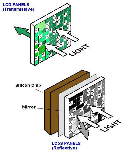
Transmissive LCD panels compared to reflective LCoS display panel technology. (Image: Source)
LCoS combines transmissive and reflective approaches. Instead of individual mirrors, it uses liquid crystals as the reflective element, with liquid crystals “applied to a reflective mirror substrate. As the liquid crystals open and close, the light is either reflected from the mirror below, or blocked. This modulates the light and creates the image.”5
Simplified schematic of an LCoS projector system. (Image: Source)
To create full-color images, LCoS displays and projectors typically use three LCoS chips, one each in the red, green, and blue channels (similar to the way an LCD projector uses three-color LCD panels). LCoS has come to dominate the market niche of “pico-projectors,” which are characterized by their small size and low power consumption.6
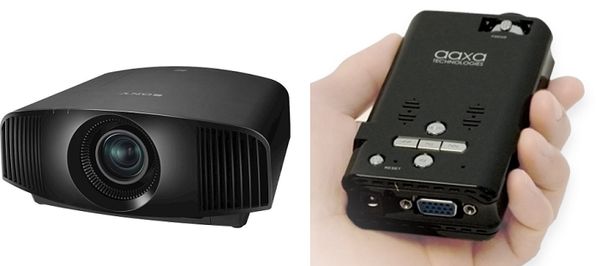
Sony’s 4K LCoS projector (left), marketed for home theater use (Image: © Sony Corporation of America), and the Aaxa P2 LCoS Pico Projector (right) (Image: © Aaxa Technologies).
LCoS Layers
LCoS microdisplays, like those used for AR/VR devices, are composed of a liquid crystal layer between one transparent thin-film transistor (TFT) and one silicon semiconductor with a reflective (pixelated) surface. A light source “shines through a polarizing filter and onto the device, and the liquid crystals act like gates or valves, controlling the amount of light that reaches the reflective surface. The more voltage a particular pixel's crystal receives, the more light the crystal allows to pass.”7
Typical component layers of an LCoS microdisplay are (bottom to top):
- Printed circuit board (PCB): the base of a display, which carries instructions and electricity to the device
- Silicon (a chip or sensor): the silicon layer controls the liquid crystal, generally with one transistor per pixel, using data from the device’s pixel drivers
- Reflective coating: reflects incoming light
- Liquid crystal: controls the amount of light that reaches the reflective coating and that is allowed back out
- Alignment layer: keeps the liquid crystals properly aligned so they can direct the light accurately
- Transparent electrode: completes the circuit with the silicon and the liquid crystal
- Glass cover: Protects and seals the system8
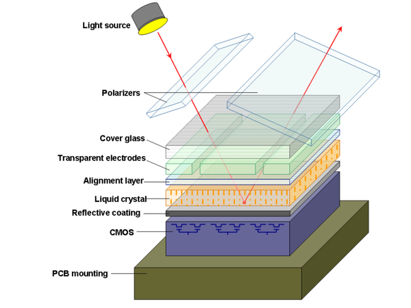
Layers of a typical LCoS microdisplay. (Image: Source, CC 3.0 Unported)
LCoS Applications
As a form of SLM, LCoS has many potential applications, including:
- Industrial projection (fringe/pattern projection – metrology, 3D-sensor, rapid prototyping, lithography)
- Industrial imaging (data displays, medical, simulation)
- Head-up displays (HUD) and head-mounted displays (HMD) in automotive, airborne, and defense industries
- High resolution non-direct view microdisplays, called near-to-eye (NTE) systems. For example, some digital camera viewfinders (called electronic viewfinders, or EVF) systems
- AR and VR applications
- Optical beam steering
- Holographic projection and storage
- SLMs for R&D and phase applications.
The high resolution, visual clarity, low energy use, and small size of LCoS microdisplays makes them particularly appealing for near-eye displays (NEDs). Interest in LCoS has been strong in the AR/VR industry, with exploration of both intensity-modulated and holographic-image-generation approaches.9 Projection-based systems such as automotive HUDs can also benefit from the advantages of LCoS.
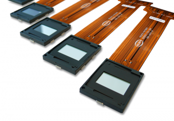
LCoS microdisplay components from Holoeye, ready for integration into virtually any type of product, from medical devices to aviation to consumer electronics. (Image © Holoeye)
Quality Control for LCoS and Other Display Types
As display technologies such as OLED, microLED, and LCoS become increasingly popular for use in AR/VR devices, and automotive and aerospace HUDs, particularly careful measurement and testing is required to ensure visual performance. Radiant offers measurement solutions designed specifically for these unique applications, built around our high-resolution ProMetric® Imaging Photometers and Colorimeters.
AR/VR Devices
The Radiant Vision Systems AR/VR Lens system accommodates the unique viewing geometries of AR/VR devices with a front-located lens aperture that enables positioning the imaging system’s entrance pupil inside headsets and glasses at the same place as a human eye. Applying wide-field-of-view (FOV) optics, the system captures an entire display up to 120° horizontal in a single measurement.
Used with Radiant’s TT-ARVR™ Software and a ProMetric imager, the AR/VR Lens enables device developers and manufacturers to evaluate critical performance qualities such as brightness, color, contrast, uniformity, and sharpness (MTF) of projected images.
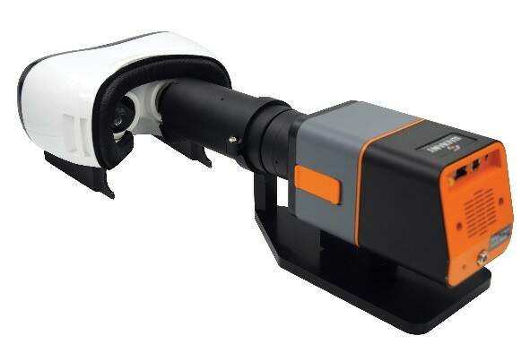
The AR/VR Lens replicates the position and size of the human pupil within a headset to capture the user’s full FOV.
Head-up Displays
HUDs pose unique measurement challenges for manufacturers, who must account for projected image luminance, contrast, and clarity regardless of ambient conditions, virtual image positions, or focal distances on an infinite viewing plane. Comprehensive HUD testing requires both photometric (light data) and dimensional (spatial data) measurements combined to ensure the accuracy of information conveyed to a vehicle operator within a rapidly changing, real-world environment.
Radiant Vision Systems TT-HUD™ Software efficiently performs light, color, and dimensional measurements with specific tests used to evaluate the quality of augmented projections, such as those emitted by HUD systems. A comprehensive HUD test solution from Radiant combines the TT-HUD software module and a ProMetric imager with electronically controlled lens to perform rapid, automated visual inspection. Tests range from brightness and contrast evaluation, to distortion, MTF, ghosting, and eyebox analysis.
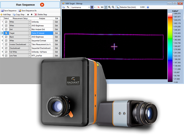
TT-HUD is paired with a ProMetric Imaging Colorimeter or Photometer, providing multiple options to achieve the field of view, pixel resolution, and cost requirements for your application.
The TT-HUD solution can test all HUD characteristics simultaneously, capturing and processing data much faster and more consistently than a spot measurement device or machine vision system. In a single hardware/software solution, TT-HUD can be used to evaluate all visual aspects of the HUD system as well as test to the specific parameters documented in automotive standards.
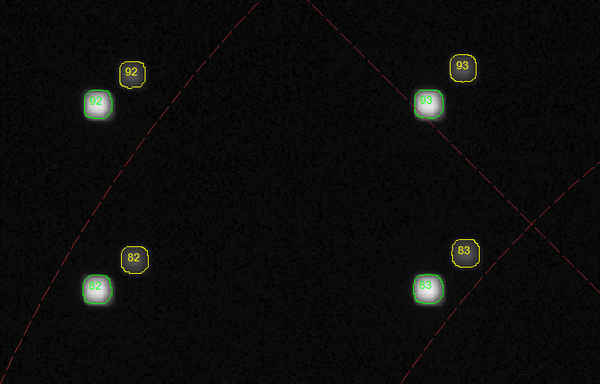
TT-HUD detects duplicate projections (overlapping or separated from the primary image) that are caused by ghosting effects using a Ghosting Analysis function.
CITATIONS
1. “Liquid Crystal on Silicon (LCos) Display Market – Growth, Trends, and Forecast (2019-20204)”, Research and Markets, June 20, 2019.
2. Lazev, G., et al., “LCOS Spatial Light Modulators: Trends and Applications”, Chapter 1 in Optical Imaging and Metrology: Advanced Technologies, First Edition, Osten, W. and Reingand, N., editors. Wiley-VCH Verlag GmbH & CO KGaA: 2012
3. “Liquid crystal on silicon”, Wikipedia. (Retrieved July 16, 2020)
4. Powell, E., “What’s so hot about LCOS technology?”, Projector Central, July 18, 2003
5. Pico Projectors Market – Forecast (2020 – 2025), Industry ARC. (Retrieved July 20, 2020)
6. “Global LCOS Projector Market Insights, Forecast to 2025”, Industry Research, January 23, 2019.
7. Wilson, T., “How LCoS Works”, How Stuff Works. (Retrieved July 16, 2020)
8. Ibid.
9. Huang, Y, et al., “Liquid Crystal on Silicon for Augmented Reality Displays,” Applied Sciences, Vol. 8, 2366. DOI 10.3990/app8122366
Join Mailing List
Stay up to date on our latest products, blog content, and events.
Join our Mailing List