Truly Automated Light and Color Measurement for Tell-Tales and Indicators

When it comes to inspecting the accuracy and uniformity of light-emitting symbols on an instrument panel, manufacturers are faced with a small quality control nightmare. Is it possible to ensure the harmonization of so many different shapes, sizes, colors, and positions of lighted features in a single space? The greatest stride thus far in light measurement over a wide area (such as a complete instrument panel) has been the application of imaging colorimeters. Colorimeters are image-based photometric measurement devices calibrated to match human visual sensitivity to brightness and color. These cameras capture high-resolution images of large areas and utilize special analytical software to apply visual inspection tools to capture data across an image. With an entire panel captured in a single image, colorimeters provide a two-dimensional environment where light and color data may be assessed for all illuminated symbols on an instrument cluster at once. Well… sort of. Once an image is captured, a complete and successful evaluation all depends on the capability of your measurement software.
The problem comes in the setup and execution of parameters in the measurement software. Although an imaging colorimeter can capture a complete instrument panel in a single image, independent tolerances must still be set for each of the criteria that you need to measure within the image. For example, a manufacturer may need to measure the collective luminance (brightness) and uniformity of all symbols on the panel, the uniformity of luminance across symbols of a certain type, the uniformity of chromaticity (color) and luminance among red symbols, blue symbols, white symbols, or analog components (like speedometer needles)… Each symbol set has unique luminance and chromaticity thresholds that allow the set to be identified from among its many neighbors, as well as analysis criteria that must be programmed into the software to ensure all symbols within the set meet a desired brightness or color threshold for each inspection to be performed. And, of course, related symbols on an instrument panel are rarely located adjacent to one another other (for example, rarely do we see all red indicators together in one space). How, then, can a set of related symbols be completely and accurately measured?
As the position of the panel relative to the
camera shifts, symbols on the panel fall outside
of the applied static points of interest.
Up to this point, setting up instrument cluster inspections through available measurement software has been a manual and time-consuming process. To distinguish and apply evaluation criteria to symbols on a panel, developers must manually draw points of interest (POI) around each symbol one at a time, defining a spatial region in the software to encompass each symbol in the image. After measuring each symbol’s light and color values, the developer can apply inspection parameters to compare values across related symbol sets. This requires that the developer define which symbols are a part of each set using luminance and chromaticity thresholds to ensure inspections are applied accurately.
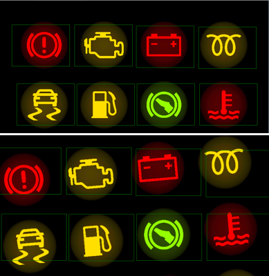
Once this is done, there is no guarantee that the programmed points of interest and thresholds will accommodate new panels on the line. This is because static points of interest applied to the image will not move from where they have originally been drawn in the software – meaning POI will not adapt to new images captured or new conditions that may result during in-line inspections for a series of panels. If the relative camera-to-panel position shifts during inspection (for instance, as a new panel enters the inspection area at a slight angle), symbols in the captured image may fall out of the scope of the applied static POI, resulting in inaccurate light measurements and potentially false results.
Complicating production inspection further, the inspection POI must be completely redrawn when a new panel with a different arrangement of symbols enters the line. The result is regular downtime for errors and changeovers, and a higher probability of inaccurate results, making panel analysis largely unreliable and in-line light and color harmonization evaluations impractical.

As the position of the panel relative
to the camera shifts, symbols on the
panel fall outside of the applied
static points of interest.
The challenge calls for smarter technology. Thankfully, Radiant’s engineering team has been busy developing just such an improvement, with the unique goal of making instrument cluster measurement and inspection simple to implement and feasible for application in changing production lines. Auto-POI, the latest feature of Radiant’s ProMetric® and TrueTest™ software, is the first to offer truly automated measurement of light and color for tell-tales and indicators across entire instrument clusters.
Using Auto-POI and an imaging colorimeter, manufacturers can easily measure and inspect multiple sets of symbols simultaneously within a wide-area image, without drawing static POI, which depend on fixed spatial tolerances. Instead, the engineer can define adaptive tolerances by entering luminance and chromaticity thresholds as numeric data points in the software, enabling Auto-POI to automatically identify which pixels in the captured image qualify for analysis, regardless of their spatial position.
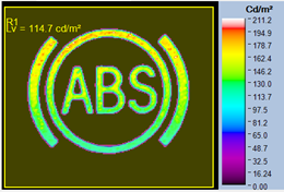
For instance, a luminance threshold can be set for Auto-POI to capture all symbols in an image that meet a minimum luminance value (for example, to evaluate all symbols that are at least 20% the brightness of the highest luminance value in an image). CIE chromaticity limits (minimum and maximum x,y or u’,v’ coordinates) can be set to further segment out target colored symbol sets from those of a common luminance set (for instance, red or blue symbols with the same luminance minimum) for a more specific evaluation. Auto-POI automatically identifies points of interest as connected blobs of pixels that meet the programmed threshold values, limiting the points of interest to only the illuminated pixels and excluding background data and noise.
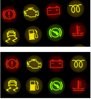
Additionally, because Auto-POI locks onto each symbol based on global data values (rather than a static spatial areas), the Auto-POI functionality enables the software to capture symbols dynamically and with precision, regardless of their positions within an image or movement of the panel in respect to the colorimeter. This eliminates any risk of lost data if panels on a production line shift or change, as was the concern with static POI. Regardless of the position of the instrument panel, the orientation of the camera, or the arrangement of symbols on a panel (such as a new line of panels entering production), Auto-POI can quickly snap onto target symbol sets within the inspection area based on the programmed light and color values. This enables the most adaptive and reliable in-line evaluation method for light and color quality and harmonization.
Auto-POI greatly reduces the setup time of light and color measurement applications for instrument clusters, as well as the time to change jobs on the line when actively inspecting symbol quality of panels in production. The adaptability of Auto-POI to changing conditions means less margin for error, fewer escapes of sub-par components into the supply chain, greater control over supplier component quality, increased up-time, and absolute quality products that meet high consumer expectations. As competitive advantage is defined by speed and accuracy, automakers can find peace of mind using smarter quality control solutions to catch errors and keep high-caliber production in motion. More than a means to this end, Auto-POI’s true value is in its experience – bringing harmony to illuminated panels, and to the manufacturing process.
- The fastest, most intuitive evaluation of complex instrument clusters
- Apply limited point of interest (POI) areas in software to measure all points on a panel at once
- Toggle between programmed luminance and color thresholds to evaluate symbol sets for cross-symbol uniformity
- Automatically find target POI even when displays are rotated or moved
Join Mailing List
Stay up to date on our latest products, blog content, and events.
Join our Mailing List